The practical answer.
An internal resistance value is incomplete without its measurement method and battery state. ACIR uses an alternating signal at a stated frequency; DCIR derives a value from a defined current change and the resulting voltage response at a specified time. Temperature, state of charge, fixture and measurement boundary affect interpretation. Compare like methods before using milliohm figures to accept cells or finished packs.
- Attach a method and conditions to every resistance limit.
- A four-terminal arrangement reduces lead-related measurement error but does not make ACIR and DCIR equivalent.
- A finished-pack result includes a different current path from a bare-cell result.
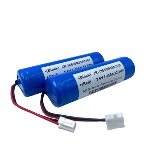
Read the method before reading the milliohm number
A report stating internal resistance below a number can appear precise while omitting the most important context. Ask whether it is an AC measurement, a DC pulse-derived result or another impedance quantity. For AC testing, retain frequency and the reported component of the response. For DC testing, retain the current change, pulse duration and voltage observation point. The same unit does not establish that the tests measure the same behavior.
Hioki describes battery testers that use a four-terminal AC method, commonly at 1 kHz for the referenced instruments. NI describes DCIR through voltage change divided by current change and explicitly notes dependence on state of charge, temperature and pulse duration. These descriptions explain different test methods; they do not prescribe an acceptance limit for any Jetray product.
A DC pulse value belongs to an observation time
Battery voltage responds over time after a current change. A value extracted immediately after the change and a value extracted later in the pulse can include different contributions to the response. The report should identify the algorithm and timing rather than describe both as a single timeless resistance. The qualified procedure also needs preparation and rest conditions so repeated measurements begin from a comparable state.
For an original arithmetic illustration, a measured voltage change of 0.10 V associated with a measured current change of 2 A gives 0.05 ohm, or 50 milliohms, at that observation point. This is only a calculation example. It specifies neither a suitable pulse for a real cell nor a pass limit. Changing the timing, state or boundary can change the extracted result.
| Report item | AC method | DC pulse method |
|---|---|---|
| Excitation | Frequency and signal conditions | Current change, duration and repetition |
| Result definition | Reported resistance or impedance component | Voltage response at a defined observation time |
| Battery state | Preparation, temperature and state of charge | Preparation, temperature, state of charge and rest |
| Connection | Fixture and sensing boundary | Force and sense boundary and synchronized measurements |
| Comparison | Same approved method and limits | Same approved pulse method and limits |
Separate fixture effects from the product boundary
At low resistance, connection details matter. A suitable four-terminal method separates the current-carrying path from the voltage-sensing path and reduces the influence of measurement leads. The test owner should still document fixture condition, sensing points and the applicable instrument method. Four wires are a measurement arrangement, not an assurance that every possible contact or timing error has been eliminated.
The chosen sensing points define what the result includes. A bare-cell measurement at its terminals differs from a completed pack measurement at its external connector. The latter can include interconnects, protective switching components and internal wiring. If a pack result is compared with a cell datasheet value, the reviewer must first reconcile those boundaries. An unexplained difference is not automatically a cell defect.
Do not open a pack or probe internal points to reproduce an article example. Require the qualified supplier or test facility to supply the agreed evidence using the approved safe procedure and fixture.
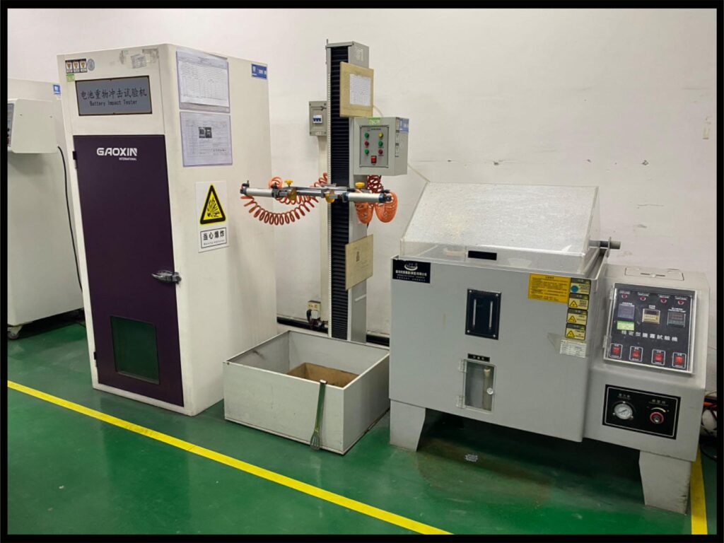
Use resistance as evidence for a defined decision
A rapid production measurement can be useful for detecting variation against a controlled baseline. A pulse-response study can help evaluate voltage support under an application-related timescale. Neither result alone establishes complete capacity, lifetime or safety. Specify which decision the test supports, then request additional evidence for the questions it cannot answer.
Avoid a purchasing rule that the lowest advertised resistance always identifies the best pack. Different capacities, cell identities, methods and current paths can make that comparison meaningless. First confirm model suitability and approved conditions. Then compare consistent results and ask how the supplier responds to outliers or a change in distribution across lots.
Reconcile supplier and buyer measurements before rejecting a lot
If two benches disagree, compare preparation, temperature, state of charge, rest, fixture, method settings and sensing boundary. Check sample identity and the time between measurements. Reproduce the agreed method before declaring one instrument or the product wrong. The difference may reveal a real issue, but the evidence needs to distinguish product variation from measurement variation.
Retain representative raw voltage and current data for pulse tests where the agreed reporting package includes them, plus the extracted values and method revision. A spreadsheet of final numbers cannot show a changed observation time or an interrupted pulse. The linked catalog references make the inquiry concrete; request the current finished-pack specification rather than applying a generic cell resistance threshold to them.
- Identify the exact test quantity and its intended decision.
- Freeze preparation, battery state, excitation and observation timing.
- Document fixture, sensing boundary and measurement capability.
- Compare results using the same method and investigate deviations before disposition.
Resistance-report questions
Can I convert ACIR into DCIR with one multiplier?
No universal conversion is established here. The methods probe different responses and depend on their conditions. Request the required method directly or an application-specific correlation supported by the supplier's evidence.
Does one acceptable resistance result prove capacity?
No. Capacity requires its own defined evaluation. Use resistance for the screening or response question it was designed to address, and retain separate capacity and finished-pack acceptance requirements.
Sources & further reading
- NI: Direct Current Internal Resistance Testing ↗
- Hioki: battery tester measurement principles and four-terminal AC method ↗
- Keysight: four-wire battery sensing and pulse measurement principles ↗
- Jetray: 18650 pack public reference ↗
- Jetray: corporate factory photo source ↗
AI-assisted editorial content fact-checked against linked primary instrument documentation. The 50 milliohm example is hypothetical arithmetic, not a test instruction or result. No universal matching limit, individual engineer review or model-specific acceptance is claimed.
Prepared for the 18650 battery packs collection. General engineering guidance does not replace a model-specific datasheet or application validation. Source review: 5 November 2026.