The practical answer.
Use the terminal style and exact battery assembly authorized by the equipment design. A button top has a raised positive contact. A flat top has a lower profile. The 18650 family name alone does not establish the finished length, contact reach or protection required by a particular holder. Check those limits against the candidate drawing and approve the installed combination before purchasing replacements.
- Specify the item being purchased first, such as a removable battery or a wired 1S1P assembly.
- Record overall length, positive contact position and holder travel as separate drawing requirements.
- Use the shortest and longest permitted combinations to review fit and contact.
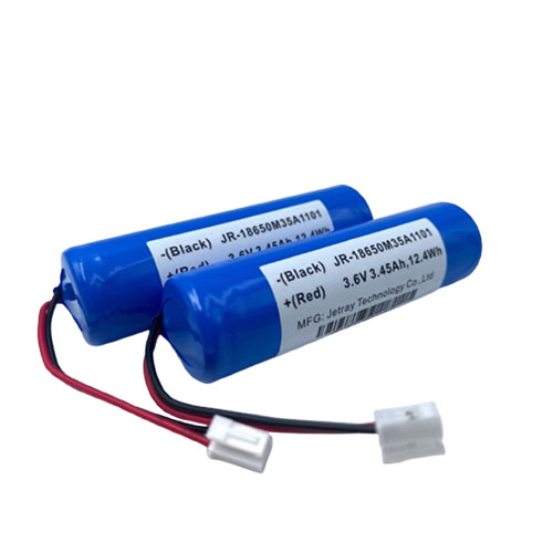
Start with the replaceable unit specified by the equipment owner
Start by identifying what comes out when the equipment is serviced. A removable cylindrical battery mates directly with contacts in a holder. A wired 1S1P pack can contain one 18650 cell but present a lead connector and a different mechanical envelope to the host. An OEM service spare needs to match the interface presented by the finished item. Changing from one service form to the other is an equipment design decision.
Jetray's 18650 reference materials identify a raised button top on some examples. That describes the illustrated contact style. It does not apply the same terminal to every 18650 pack in the catalog. The related Jetray pages are single-cell assembly references. Request the approved finished drawing to determine which termination a quotation covers.
| Item under review | What touches the host | Drawing or record to request |
|---|---|---|
| Removable battery with raised terminal | Terminal surfaces meet the holder contacts | Finished length and diameter limits, positive protrusion and insulating shoulder |
| Removable battery with lower profile terminal | Holder contacts must reach the specified contact surfaces | Terminal face location, holder reach and contact engagement range |
| Wired 1S1P assembly | A lead set or connector meets the equipment harness | Finished pack outline, lead exit, connector part number and pin assignment |
Compare the actual contact geometry at both tolerance limits
For a removable battery, identify the surfaces used as the length datums and the usable positive contact area. A raised positive contact may be necessary when the device's positive contact sits behind an insulating shoulder. A longer candidate can solve the reach problem and still leave too little spring travel for the cover to close properly. The drawing review should resolve both conditions separately.
Suppose a hypothetical holder contact is 0.8 mm behind its insulating stop at one tolerance extreme. A candidate's minimum positive protrusion is 0.6 mm, both dimensions taken from the same assembled datum and with no other permitted movement. The simple stack leaves a 0.2 mm reach shortfall. A candidate whose protrusion reaches the contact then needs a separate check at maximum overall length and the shortest permissible holder. The example dimensions are invented to show the method. Use the design's tolerances and measured samples for the actual decision.
Ask whether the maximum finished length includes sleeves, insulation and any protection hardware present on the quoted configuration. Drawing conventions vary. Panasonic's industrial catalog lists dimensions per model within the 18650 family, and the Nitecore MT42 device manual identifies a button-top 18650 as compatible and a flat-top unit as incompatible for that device. Treat both as evidence that the specific battery and host need separate checks.
Treat fit, retention and electrical compatibility as separate approvals
A battery can enter the cavity while the spring contact sits near the edge of its travel. Under normal movement, a marginal contact can interrupt power even when the device worked during first assembly. Conversely, excessive compression can load the cover or constrain the insulating parts. Ask the equipment team to define the intended mechanical check based on its own drawings and service conditions.
When reviewing a candidate, document contact engagement, enclosure closure and retention on an authorized sample. The equipment team should use its agreed functional checks at the intended voltage and load with the battery configuration it actually plans to buy. Review the exact charging range, permissible current and protection arrangement on the product specification. Terminal appearance alone cannot establish those limits.
If an approved alternative can fit alongside a different service battery, distinguish the parts in the equipment documentation and stock locations. The supplier's part number, drawing revision and allowed host revisions matter more than a catalog description such as 18650 3.6 V.
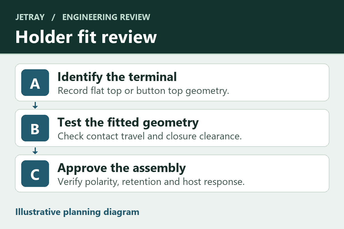
Give purchasing a finished-item specification
If an equipment drawing is unavailable, request the authorized replacement part number from the host maker and arrange a fit review. Altering a terminal or adding an improvised spacer changes the approved interface and can create an unintended current path. An approved alternative should fit with the original holder as designed or have a separately documented equipment revision.
- Identify the replaceable unit, the installed orientation and the equipment revisions to be supported.
- Ask for a dimensioned drawing of the exact finished item, including terminal geometry or lead exit as applicable.
- Have the equipment team compare contact reach and closure across drawing tolerances and inspect an authorized sample.
- Match the electrical specification and protection scope to the host and charger requirements.
- Record the approved part and change process so the supplier can identify a different terminal or assembly before shipment.
What a replacement buyer should ask about top style
Is every button-top 18650 protected?
The top style describes the terminal geometry. Protection is a separate property of the supplied item. Request the manufacturer specification and the exact mechanical drawing to verify both.
Does 1S1P mean the battery is a drop-in holder replacement?
1S1P identifies one cell in the series and parallel arrangement. It says nothing about an external holder, the presence of wires or the finished enclosure. For a wired assembly, the outer dimensions and connector interface control the fit with the equipment.
Sources & further reading
- Jetray 18650 battery pack catalog and 1S1P examples ↗
- Panasonic professional battery catalog, page 26 model-specific 18650 dimensions ↗
- Nitecore MT42 device manual, battery compatibility table ↗
The holder stack is an illustrative drawing exercise. The article does not establish the terminal style or approval for a particular pack, holder or flashlight.
Prepared for the 18650 battery packs collection. General engineering guidance does not replace a model-specific datasheet or application validation. Source review: 5 November 2026.