The practical answer.
An 18650 pack's thermal suitability depends on the assembled current path, repeated duty cycle and installed heat-rejection path, not only the cell's advertised discharge current. Evaluate the hottest relevant locations and temperature differences under approved conditions, including interconnects and electronics. Agree sensor coverage, acceptance limits and the exact enclosure and installation used for qualification.
- A bare-cell operating limit is not a finished-pack thermal approval.
- Average current can hide heating from a repeating pulse profile.
- One enclosure temperature cannot establish every internal location's condition.
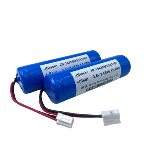
Draw the thermal boundary around the installed assembly
Start with what surrounds the pack in service. The equipment enclosure, mounting surfaces, neighboring heat sources, airflow and permitted orientation can change how heat leaves the assembly. A pack tested openly on a bench does not automatically represent the same pack inside a compact housing. Provide the supplier with the installation conditions and distinguish normal operating arrangements from abnormal or restricted ones.
The cell manufacturer's data remain important, but they describe their stated cell conditions. The finished pack adds interconnects, protective electronics and a mechanical arrangement. A 2024 national-laboratory thermal-characterization paper reports additional module-interconnect heat and nonuniformity associated with cooling arrangements in its studied systems. Those findings support evaluating multiple assembly levels; they are not measurements of Jetray packs.
Preserve the timing of the load instead of using average current alone
Resistive heating depends on current squared for an unchanged resistance. As an original illustration, a path carrying 10 A for half a cycle and zero current for the other half has an average current of 5 A. Its mean squared current is 50 square amperes, compared with 25 for a steady 5 A. The corresponding RMS current is about 7.07 A. The pulsed example therefore produces twice the resistive heating in that unchanged path, despite equal average current.
A real battery's heat generation is more complex than this fixed-resistance model, and its resistance and heat paths vary with state and temperature. The calculation does not predict a pack temperature. It demonstrates why the supplier needs pulse duration, repetition and recovery intervals as well as average demand. Include charging or other events that are part of the permitted duty sequence.
| Input | Why it matters |
|---|---|
| Continuous and repeating pulse profile | Determines time-dependent heat generation |
| Starting and ambient conditions | Defines the initial state and available heat rejection |
| Host enclosure and mounting | Changes conduction and airflow paths |
| Interconnect and electronics revision | Identifies non-cell heat sources |
| Temperature locations and sensors | Defines what the measurements actually represent |
| Acceptance and stopping rules | Separates permitted operation from protective response |
Look for hot locations and gradients, not only a maximum display
The hottest point may not be where a convenient sensor is installed. Cells near a heat source, enclosed internal regions, switching electronics and connectors can experience different conditions. Ask the supplier how measurement locations were chosen and what evidence supports the relationship between the monitored points and the limiting locations. Do not infer internal temperature from a single cool outer surface.
Temperature differences also matter because cells in one assembly can experience different operating histories. The appropriate allowable difference depends on the design and application; this article does not prescribe a universal gradient limit. Request the project's acceptance criteria and the evidence supporting them. A thermal image or isolated maximum value without emissivity assumptions, location and test state can be hard to interpret.
Protection sensing and development characterization serve related but different purposes. A production pack may use fewer sensors than a qualification setup. Ask how that reduced monitoring arrangement was justified, rather than assuming every characterization point becomes a production sensor or that a single controller temperature represents cell temperature.
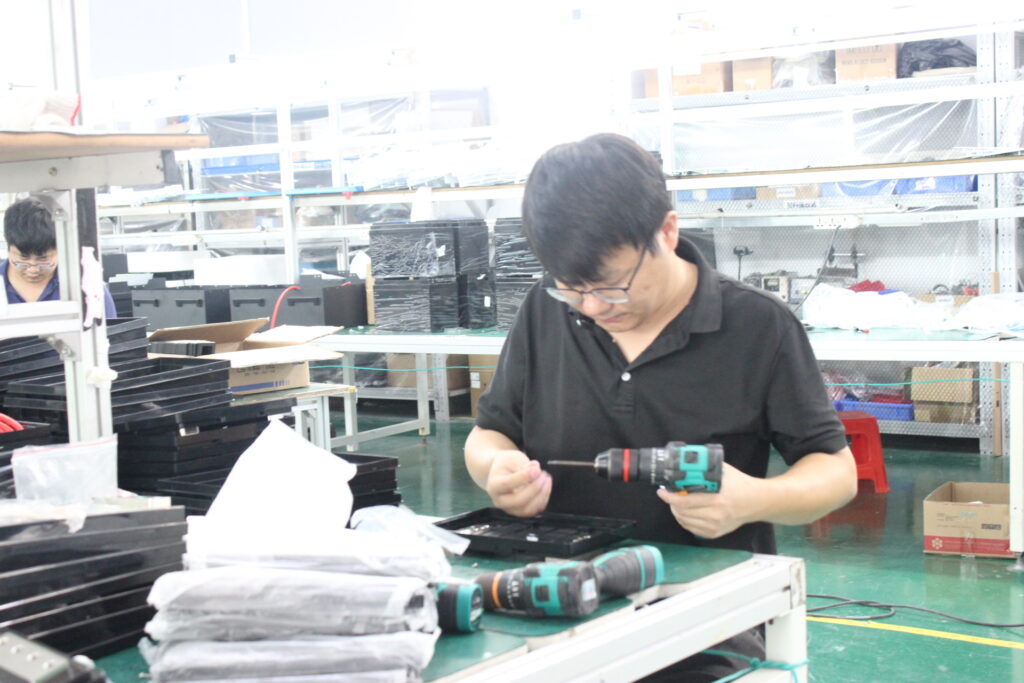
Include interconnects, protection and the external interface
A cell-only explanation can miss heat generated elsewhere in the current path. Ask which interconnects, switching components and connectors are included in the thermal review. Manufacturing variation or a changed contact arrangement can affect local heating even if the approved cell model remains unchanged. Retain the assembly revision and the actual production harness used for validation.
These are supplier engineering and process-control questions, not instructions for changing welds, removing insulation or modifying protection. Require evidence from qualified personnel using an approved setup. If a hotspot appears, preserve the load and temperature records and ask for a controlled investigation. Do not assume that adding cooling around the enclosure resolves an internal connection problem.
Agree what constitutes a representative thermal acceptance run
Define the relevant mission, starting state, ambient condition, enclosure and airflow before the run. Identify whether the requirement concerns a single mission, repeated operation toward a stable pattern, or a charge-and-discharge sequence. A short demonstration can miss accumulated heat, while an artificial continuous overload may lie outside the intended product envelope. The qualified test plan should reflect the actual requirement and approved limits.
Retain temperature histories, electrical demand, equipment states and any protective events. State why the run stopped and whether the required task was completed. A claim that temperature stayed acceptable is incomplete unless acceptable has a documented meaning for the measured locations and conditions. The linked references are starting points for a project discussion, not blanket approvals for an enclosure or duty cycle.
- Freeze the installed enclosure, harness and approved duty sequence.
- Agree relevant heat sources, measurement locations and acceptance criteria.
- Evaluate repeated behavior with qualified personnel and approved safeguards.
- Retain traces and reassess changes that affect current or heat rejection.
Thermal procurement questions
Can the maximum cell discharge rating approve the whole pack?
No. It is one cell-level input with its own conditions. The finished assembly and installation require their own electrical and thermal evaluation, including the protective and external current path.
Which changes should trigger review?
Review changes to cells, interconnects, protection components, enclosure, mounting, airflow, harness or the load profile. The supplier and equipment owner should agree which changes require renewed evidence rather than assuming a previous thermal result covers a modified system.
Sources & further reading
- National laboratory research record: Li-ion Battery Thermal Characterization for Thermal Management Design, 2024 ↗
- Molicel: INR-18650-M35A official data sheet version 1.4 ↗
- Jetray: 18650 public pack reference ↗
- Jetray: corporate factory photograph source ↗
AI-assisted editorial content fact-checked against linked primary research and manufacturer documentation. The RMS example is illustrative arithmetic, not a temperature prediction or completed Jetray test. No universal thermal limit or individual engineering review is claimed.
Prepared for the 18650 battery packs collection. General engineering guidance does not replace a model-specific datasheet or application validation. Source review: 5 November 2026.